HYDRAULIC COMPRESSOR
1. GENERAL INTRODUCTION & APPLICATION:
Hydraulic Compressor (Motorized Joint Machine) are usually used to connect two different
lengths of conductor together by compressing the mid-span joint into which the ends of the
two lengths have been inserted; Or used to connect the conductor to the tension tower by
compressing the dead end clamp with the fitted-in conductor. A complete set of hydraulic
compressor consists of one press head and one power unit ( either gasoline engine or diesel
engine or electric one) which are jointed together with two lengths of oil hoses and fast/screw
type coupling connectors.
2. SPECIFICATIONS:
2.1. COMPRESSION (PRESS) HEAD:

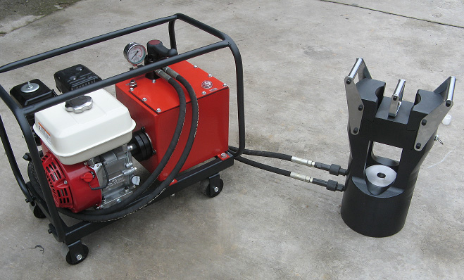
Fig.1 Hydraulic Compressor with Power Unit
2.3 DIES FOR ALUMINUM / STEEL COMPRESSION
Die for steel compression is made from steel grade 42CrMo, and die for aluminum compression
is made from steel grade 40Cr . Proper heat treatment is also a must to increase the hardness.
Sizes of dies are determined based on the specific sizes of joints.
Surface treatment is by zinc galvanization or blackening (see fig.7).
2.4. COMBINATION OF COMPRESSION HEAD AND POWER UNIT IN APPLICATION:

Remark: Specific working pressure (W.P.) of the power unit can be preset within the range of 63Mpa to 80Mpa
at factory according to user’s requirements, but compression width of the dies should be correspondingly
determined to match the practical application. Working pressure of 65Mpa to 75Mpa is recommendable
to prolong the working life of most of the components.
3. OPERATIONAL NOTES
Before start, first check the oil level in oil tank and in gasoline engine tank; set the control handle
of head valve set at medial(pause) position ( there are three positions for the handle: working
position, medial position , returning position); connect the female connector of hose to the male
connector on the compression(press) head ,and make sure they are connected reliably.
Mount the die (including object to be pressed) inside the cavity of press head.
Activate gasoline engine by hand pulling with the pulling rope starter, and adjust the throttle to the
maximum after the engine is running stably.
Turn the head (control) valve handle to working position; hydraulic oil comes out through one of
the delivery valve so as to push the piston of compression head upwards and make die close com-
pressing the joint inside to desired shape. After that, turn the handle back to medial position, and then further turn it up to returning position so as to have the piston returned to original position.
As soon as the piston return to original position, turn back the handle at medial (idle) position.
4. NOTES FOR MAINTENANCE
4.1. Oil pump is normally filled with hydraulic oil grade 32 suitable for working temperature within
the range of 5 degree centigrade to 60 degree centigrade; if the temperature is higher, higher
grade oil shall be used.
4.2. Oil tank must be filled with oil up to such a degree that oil level reach or even goes over the
Oil Level Mark on one side of the oil tank (refer to fig.2). The oil pump inside the oil tank
must sink completely below oil level so as to avoid getting too hot during operation.
4.3. Every time the oil is to be replaced with new one, filter of above 80 mesh must be used to
filter the new oil when it is being poured into the tank.
4.4. The control handle of head valve set should be set at medial position before starting the engine.
4.5. Working pressure is preset at factory, and it should not be raised arbitrarily by the user; in case
it needs adjustment, to avoid damage of compressor, it should not be reset above 80Mpa.
Besides, it is well advised to avoid turning the screw bolt of safety valve in too much; one
round of turning for adjustment of pressure is sufficient. The needle of the safety valve is made
from carbide, and accordingly it is very wear-proof. But on the other hand, it is brittle. So if the
needle gets stuck while being turned in, further tampering of the screw bolt might give rise to
breakage of the valve needle.
4.6. Regular cleaning of mesh filter and inside of oil tank is well advised and hydraulic oil shall be
replaced with new ones on regular basis.
4.7. If the compressor is to be put idle for longer than two weeks, it is well advised to turn off the
gasoline entrance switch of the engine, and burn off the remains of gasoline in the carburetor of
the engine so as to prevent route blockage of gasoline entry inside carburetor in future
5. TROULESHOOTING
5.1. Lower Pressure
* First check whether the oil level is at or above the Oil Level Mark(fig.2);if not, add oil to the tank.
* Open the top plate of oil tank and check whether and where there is oil leakage inside.
If safety valve leaks, unscrew the outer nut of safety valve loose, and screw the bolt of safety valve
downwards and clockwise with a screwdriver to raise the pressure(screw the bolt anti-clockwise
and upwards to reduce the pressure);if head valve set leaks, replace its upper cover assembly(assy.)
including 3 nozzles ( refer to fig.4) with new ones ( take off it’s upper cover assy. with L shaped
spanner, and pull out the 3 nozzles with a pair of pincers).
* Adjust safety valve
* Clean mesh filter
5.2. Oil Seal Leakage
* The repair work is based on the principle of replacing the oil seal where leakage has happened.
* Replacement of Frame Rubber Seal ( see fig.3)
Take off the engine. Adjust the position of oil tank so as to position the frame seal flat side up
or a little slantwise( to avoid leakage when the old frame seal is taken off) .Next prize the frame
rubber seal out with a screwdriver, and then push a new frame rubber seal in.
5.3 No Display from Pressure Gauge
* Pressure gauge gets damaged: replace it with a new one;
* Safety valve remains open or it is clogged with dirt: adjust pressure of spring of the safety valve
or clean the safety valve.
* Safety valve has been worn out: replace needle valve and valve seat of the safety valve or the
complete safety valve.
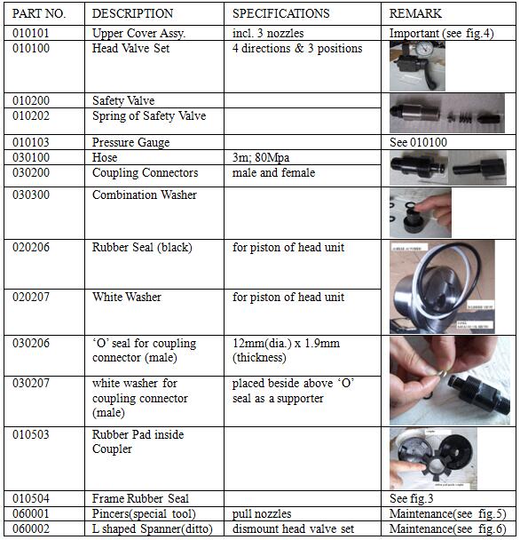
6. SPARE PARTS